


Audi A3 8V Digital Instrument Cluster Installation Guide for 2014-2020
How to Install an Audi A3 8V Digital Instrument Cluster (2014-2020)

This guide documents the installation route for a compatible Audi A3 8V / MQB vehicle that still uses the original analogue needle cluster. The work is not a simple screen swap: the original instrument cluster is removed, opened on a protected bench, and the required original control-board hardware is installed into the new 10.23-inch LCD cluster assembly before the unit is tested in the vehicle.
Quick fitment answer: the route applies when the vehicle is an Audi A3 8V / MQB within the documented 2014-2020 range and the original analogue cluster shape matches the installation reference. If the vehicle already has a factory digital cockpit or the cluster housing differs, confirm the route before ordering.
Confirm the Audi A3 8V Route Before Removal
A model year is not enough on its own. Fitment is judged by the A3 8V / MQB platform and the original analogue instrument-cluster form shown in the installation sequence.
Correct platform
Audi A3 8V / MQB generation only; it is not the Audi A3 8P or the newer 8Y route.
Original cluster
The vehicle must still use the original analogue needle cluster route shown in the video sequence.
RHD / powertrain
RHD export, diesel and hybrid routes are included in the supplied material when the original cluster layout matches.
Stop and confirm
Do not follow this route for an existing factory digital cockpit or a visibly different cluster shape.

Compatibility rule: compare the original mechanical cluster shape with the documented installation route. When the shape, dashboard opening or required display function is uncertain, send clear photos before purchase or disassembly.
What the Audi A3 8V Digital Cluster Route Adds
This section keeps the product information relevant to the installation decision. It explains what is being fitted and why internal transfer is part of the job.
Non-destructive harness route
The normal installation uses the factory-connection path without drilling, cutting or splicing the original vehicle wiring harness.
Linux-based display system
The supplied product information identifies a Linux-based cluster system, approximately 3-second startup behaviour, a 10.23-inch 1920 × 720 display and multiple Audi / VW-style interface options.
Original control-board path
The retrofit is built around the retained original instrument-control hardware path. After fitting, verify vehicle data, warning indicators, menu response and applicable steering-wheel control behaviour before final closure.
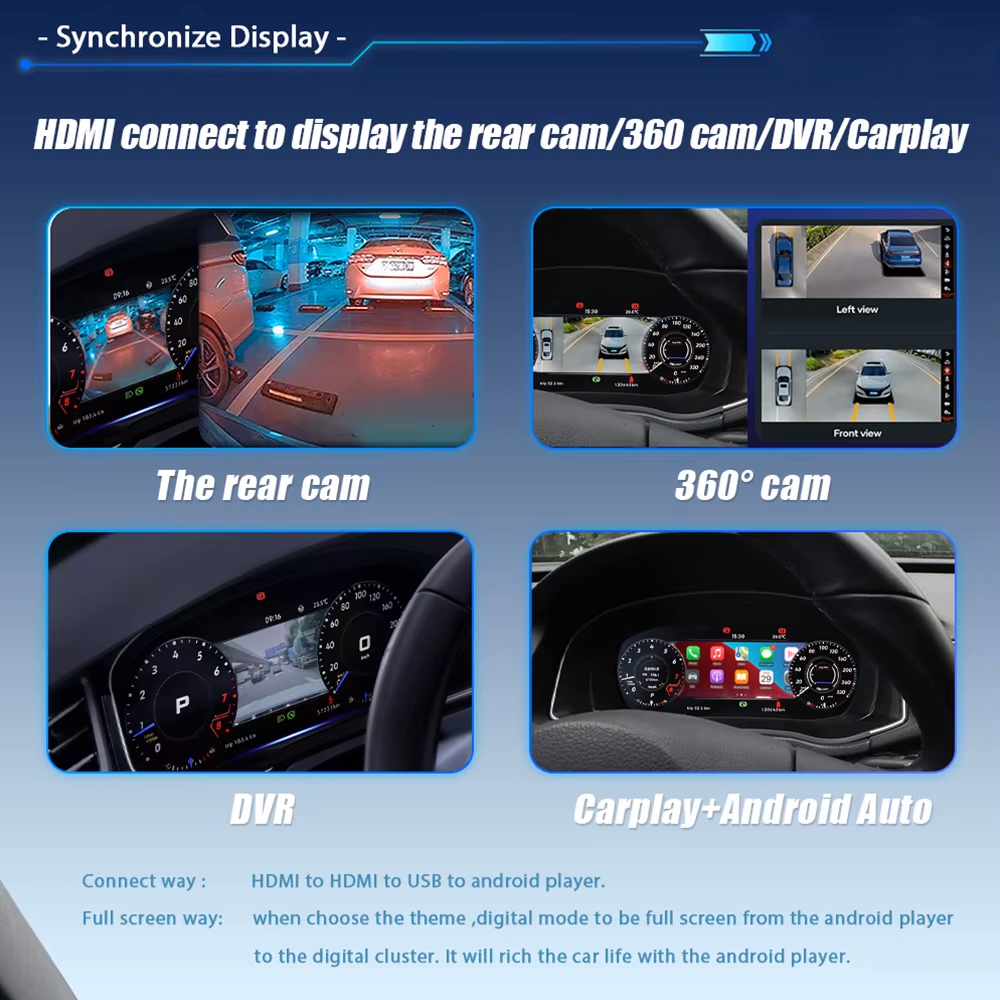
Display-function boundary: phone mirroring, CarPlay-style projection and cluster-side map display depend on the supplied hardware and connection route. A matching housing does not by itself confirm every display function.
Prepare the Vehicle and Bench Before Pulling Trim
Use a disciplined work order for this Audi A3 8V route: confirm the cluster match, protect the vehicle, prepare a clean workbench and prevent electronic damage before the original cluster is opened.
Vehicle preparation
- Photograph the dashboard and powered-on original cluster.
- Note any warning already visible before removal.
- Protect visible trim before using removal tools.
- Set the steering position to provide working clearance.
Tools and bench
- Use plastic trim tools and the correct fastener tools.
- Prepare a padded, clean work surface.
- Keep a tray for screws, clips and transferred parts.
- Do not let the removed cluster hang from the harness.
Electronic protection
- Release body static before exposed-board work.
- Hold PCB edges, not electronic components.
- Keep the original buzzer and any original sub-board identified.
- Never use the LCD face as a pressure point.
LCD handling rule: support the new digital cluster by its frame and housing. Do not press the centre of the LCD when seating the shell or aligning the unit in the dashboard.
Record the Original Display Before Removing the Cluster
This baseline is your reference for final inspection. It prevents an existing warning, setting difference or display expectation from being mistaken for a new installation problem.
Record before removal
- Photograph the original cluster while powered on.
- Record any warning indicator already present.
- Note the displayed units, language and visible data.
- Confirm whether phone projection or map display is required after installation.
Use the record after fitting
- Compare visible warnings and status information.
- Check speed, RPM, fuel, temperature and door indication.
- Confirm control response and the required menu settings.
- Photograph the software-version screen before any software support request.
Watch the Full Audi A3 8V Installation Video Before Starting
The written procedure below follows this iKAGOO workshop video sequence. Watch it once in full before dismantling, then return to each stage while working.
Follow These Steps in Order
The 11 installation images from the Audi A3 procedure are retained below and reorganised into four working stages. Do not skip from trim removal directly to final reassembly without completing the bench-transfer checks.
Remove the Original Cluster from the Vehicle
Verify the starting condition, create access and release the factory connector correctly.

Confirm the original analogue layout
Photograph the original cluster and confirm that the visible housing matches this retrofit route before removal.

Release the cluster surround
Use trim tools progressively; avoid levering one corner aggressively or marking the visible trim.

Remove the fixing screws
Keep the mounting screws in order for reuse when the upgraded assembly is returned to the dashboard.

Disconnect the factory harness
Support the cluster, release the connector lock and unplug it without twisting or pulling the vehicle wiring.
Open the Original Cluster on a Protected Bench
Move from vehicle work to controlled electronic handling before separating the original housing.

Open the rear shell
Work on a padded bench, discharge static and release the shell without damaging clips or exposed electronics.

Lift out the internal core
Hold the internal assembly by safe edges and keep its removed components organised for transfer.
Transfer the Original Hardware into the 10.23-Inch LCD Assembly
The retained original control-board route is the defining step of this conversion.

Remove required original parts in sequence
Note the position and orientation of each retained part before moving it into the new cluster assembly.

Prepare the retained board path
Keep the original control-board assembly, buzzer path and any present auxiliary board with the transfer route.

Seat the board in the new housing
Align the transferred assembly so it lies flat and the connector path is not trapped or strained.

Close the housing carefully
Recheck the internal seating, then close the shell by its outer structure without pressing the LCD face.
Inspect, Reconnect and Test Before Final Trim Closure
A powered screen is not the final sign-off. Verify data, warnings and controls while the trim is still accessible.

Inspect the rear connector side
Confirm that the housing closes evenly, retained parts remain in place and the connector area is clear before refitting.
Return the assembly to the vehicle
- Reconnect and lock the factory harness fully.
- Seat the upgraded cluster without closing all trim immediately.
- Power on and compare the installed display with the baseline record.
- Complete trim reassembly only after the final check passes.
Retained Original Hardware Must Be Checked Before Housing Closure
The A3 step images establish the physical transfer route. The additional internal images below are clearly marked shared internal assembly references from a related iKAGOO Audi digital-cluster procedure; they illustrate the same retained-board and buzzer inspection principle and are not A3 exterior-trim photographs.
Required checks
- Discharge static before handling the original internal boards.
- Hold the PCB by its edges rather than touching electronic parts.
- Retain the original buzzer / warning-sound path where it is present.
- Keep any original auxiliary board in the correct position and orientation.
- Verify connector seating before closing the LCD housing.
Stop before reassembly if...
- A board or small auxiliary component has been left outside the assembly.
- The buzzer path is no longer present or cannot be identified.
- The rear connector does not seat cleanly.
- The housing needs force or screen pressure to close.
- Any component orientation no longer matches the original layout.


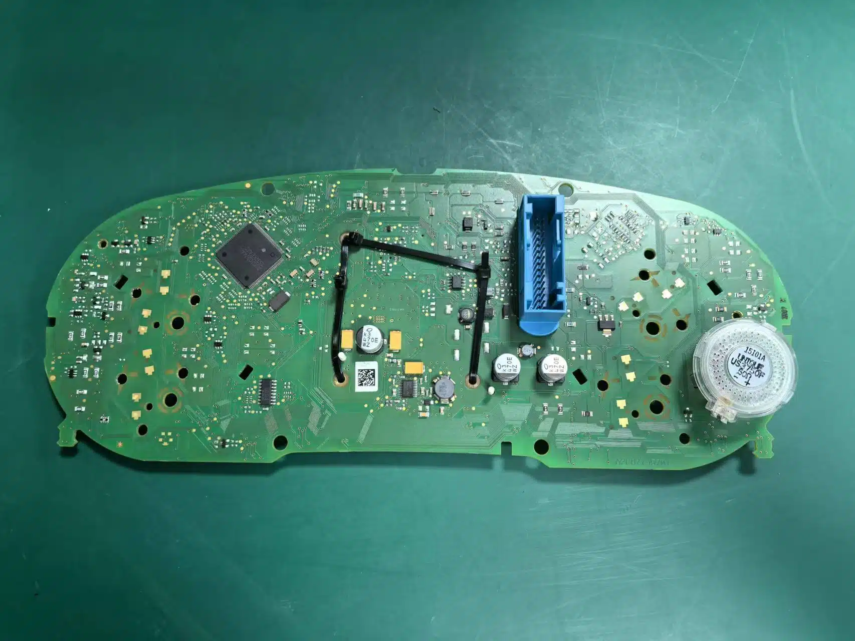

Why this step matters: leaving out the original buzzer or an applicable retained board can create instrument faults or incorrect displayed information after reassembly. Complete this inspection before the digital cluster returns to the dashboard.
Check the Installed Cluster Before Closing the Trim
Use the original record from Step 0. The final inspection is not complete until the vehicle information, warnings, menus and expected display route have been reviewed on the actual car.
| Final check | What to verify before final trim closure |
|---|---|
| Initial power-on | The cluster powers on normally and the display remains stable. |
| Vehicle information | Check visible speed, RPM, fuel, temperature, door information and any warning indication against the baseline record. |
| Menu and daily-use settings | Confirm language, speed units, brightness, date/time where applicable, and the preferred menu or UI layout. |
| Control response | Confirm the applicable steering-wheel or vehicle control input can move through menu items and confirm selections. |
| Projection / phone-link expectation | If phone mirroring, CarPlay-style projection or map display is required, verify the supplied display route rather than assuming fitment guarantees this function. |
| Software support record | Photograph the software-version screen before requesting OTA, online or USB update support. |


Final verification rule: do not close the trim immediately after the screen lights up. Compare the display against the original record and check the menus, warnings, controls and required display functions first.
After installation: complete the basic control and setting checks
- Confirm menu control. Use the applicable vehicle control input to enter the digital-cluster menu, move between items and confirm a selection.
- Set daily-use preferences. Check language, measurement units, brightness and the preferred display layout available on the supplied unit.
- Review displayed vehicle information. Compare fuel, speed, RPM, door-status and visible warning indications with the original baseline recorded before removal.
- Record software information. Photograph the version-information screen before requesting any online or USB software route.
- Only then close the trim. Complete the dashboard closure once the cluster sits correctly and the checks above have passed.
For the full day-to-day menu and display-function explanation, use the linked iKAGOO VW / Audi Digital Cluster User Guide in the next section.
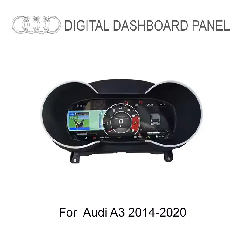
Check the Supplied Audi A3 8V Cluster Kit Before Installation
The kit is not only a display shell. Before bench work starts, compare the delivered cluster assembly and supporting harness items against the product-route references below.

Use the Correct Settings, Projection and Software Support Route
The physical installation and the post-installation support tasks are separate. Once the A3 cluster has passed its first-boot checks, use the relevant iKAGOO page for day-to-day settings, display-route decisions or version-matched software updates.
VW / Audi Digital Cluster User Guide
For navigation, UI selection, maintenance display, time and language, calibration notes and regular operation.
Open User GuideCarPlay and Display Route Guide
For phone mirroring, CarPlay-style projection or cluster-side map display questions.
Open Route GuideOnline / USB Update Guide
For supported updates after photographing the installed version screen and confirming the correct package route.
Open Update GuideOTA and remote update route
The supplied A3 material includes OTA / remote upgrade logic for supported product versions. Treat this as a version-matched software route, not a reason to apply unconfirmed files.
Product demonstration reference
For a quick installed-display reference, use the A3 product demonstration video after the fitment route has been confirmed.
Update rule: if the display powers on but data, warnings or controls do not look correct, recheck physical installation, retained hardware, buzzer path and connector seating before treating the issue as a software-update request.
Already Own a Supported Volkswagen or Audi Digital Cluster?
If you already own a supported Volkswagen or Audi digital instrument cluster and require an applicable software upgrade package, purchase the supported software route through FixMyDash with the selected 1-year or 2-year package-related support period where offered.
Before ordering, provide a clear photo of the installed software-version screen so the applicable software package route can be identified.
Buy the Matching Audi A3 8V 10.23-Inch Digital Instrument Cluster
Start from the exact Audi A3 8V product route used by this installation procedure. Confirm the original analogue-cluster shape, model year, LHD / RHD configuration and required display functions before completing the order.
Optional DDP route: for eligible destinations, customers may request an optional Delivered Duty Paid import-charges prepayment assessment before shipment. DDP is not tax-free or duty-free shipping; only import charges stated in an accepted optional quotation are prepaid through the supported route.
Frequently Asked Questions
Is this guide for every Audi A3 from 2014 to 2020?
No. This procedure is for the Audi A3 8V / MQB route where the vehicle still uses the original analogue needle cluster shown in the iKAGOO installation video. Confirm the actual cluster shape before purchasing or dismantling the dashboard.
What is the confirmed display size for this Audi A3 8V route?
The confirmed display size is 10.23-inch. Product-page text, images and related installation references should use the same size consistently.
Does this route cover right-hand-drive, diesel and hybrid vehicles?
The supplied A3 route identifies RHD export, diesel and hybrid applications, provided the original mechanical cluster shape matches the documented route. Confirm the vehicle details and original cluster photo before ordering.
Can I confirm fitment by model year only?
No. Use the original mechanical-cluster shape and dashboard opening shown in the installation reference together with the vehicle year and steering-side configuration.
What does plug-and-play mean for this digital cluster?
It means the matched installation uses the factory-connection path without cutting or splicing the original vehicle wiring harness. Removal of the original cluster, retained-hardware transfer, reassembly and final verification still apply.
Why must the original buzzer and any sub-board be retained?
This route uses retained original instrument-control hardware. Leaving out an applicable buzzer path or auxiliary board can create faults or incorrect vehicle-information behaviour after installation.
What is the most important handling rule during transfer?
Discharge static before exposed-board work, hold the PCB by its edges and do not press the LCD face while closing or aligning the new housing.
Is the job complete once the screen powers on?
No. Before closing the trim, compare the installed display with the original record and check visible vehicle data, warning indicators, controls, menu settings and any expected display route.
Where do I find settings and software-update instructions?
Use the iKAGOO owner guide for daily menu functions, the projection-route guide for phone-display or CarPlay questions, and the Online / USB Update Guide after recording the installed software version.
What if I already own a supported cluster and only need a software upgrade package?
Use the separate FixMyDash software-package purchase route shown above. It is for compatible existing supported Volkswagen / Audi digital instrument clusters and is separate from hardware repair or installation-fault resolution.








Add comment
You must be logged in to post a comment.